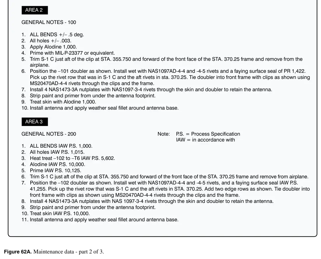
Figure 62A: Maintenance data - part 2 of 3
Practice
Sign in to practice with this figureText in this figure
GENERAL NOTES - 100 1. ALL BENDS +/– .5 deg. 2. All holes +/– .003. 3. Apply Alodine 1,000. 4. Prime with MIL-P-23377 or equivalent. 5. Trim S-1 C just aft of the clip at STA. 355.750 and forward of the front face of the STA. 370.25 frame and remove from the airplane. 6. Position the –101 doubler as shown. Install wet with NAS1097AD-4-4 and -4-5 rivets and a faying surface seal of PR 1,422. Pick up the rivet row that was in S-1 C and the aft rivets in sta. 370.25. Tie doubler into front frame with clips as shown using MS20470AD-4-4 rivets through the clips and the frame. 7. Install 4 NAS1473-3A nutplates with NAS1097-3-4 rivets through the skin and doubler to retain the antenna. 8. Strip paint and primer from under the antenna footprint. 9. Treat skin with Alodine 1,000. 10. Install antenna and apply weather seal fillet around antenna base. AREA 2 GENERAL NOTES - 200 1. ALL BENDS IAW P.S. 1,000. 2. All holes IAW P.S. 1,015. 3. Heat treat –102 to –T6 IAW P.S. 5,602. 4. Alodine IAW P.S. 10,000. 5. Prime IAW P.S. 10,125. 6. Trim S-1 C just aft of the clip at STA. 355.750 and forward of the front face of the STA. 370.25 frame and remove from airplane. 7. Position the –102 doubler as shown. Install wet with NAS1097AD-4-4 and -4-5 rivets, and a faying surface seal IAW P.S. 41,255. Pick up the rivet row that was S-1 C and the aft rivets in STA. 370.25. Add two edge rows as shown. Tie doubler into front frame with clips as shown using MS20470AD-4-4 rivets through the clips and the…